Side Camera Installation Guide for Dash Cam Pro 220
Note: The side camera channels might not be turned on by default. If after installation the channel is not coming through, please reach out to supportvideoprotects@jjkeller.com to have the channels updated correctly.
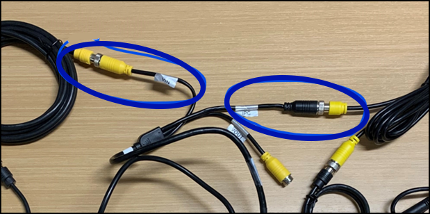
Proper Connection Points
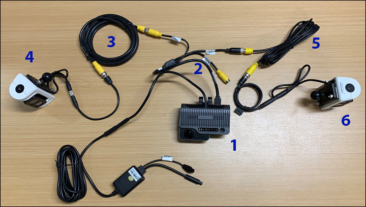
| 1 | Main Camera | Dash Cam Pro 220 |
| 2 | Video Out Cable | Connects the side cameras to the main camera |
| 3 | 4-Pin Extension Cable | Connects to the “VIN” plug on the Video Out cable and the camera adapter cable. These extension cables come in various lengths – be sure to measure the distance from the side camera mounting point back to the main camera and allow for a little extra slack so you have enough cable. |
| 4 | Left (Driver Side) Camera & Power Adapter Cable | The side cameras are side specific - Be sure to use the 4-pin camera (Model Mini C24 - SVT-A621GN-0W1EB) on the left side of the vehicle |
| 5 | 6-Pin Extension Cable | Connects to the “IPC” plug on the Video Out cable and the camera adapter cable. These extension cables come in various lengths – be sure to measure the distance from the side camera mounting point back to the main camera and allow for a little extra slack so you have enough cable. |
| 6 | Right (Passenger Side) Camera & Power Adapter Cable | The side cameras are side specific - Be sure to use the 6-pin camera (Model IP927C24M-A) on the right side of the vehicle |
Installation
1) Ensure that the main camera, the Dash Cam PRO220, is installed in the vehicle per the installation instructions found in the online guide: Dash Cam Pro220 Install Guide.
2) See Side Camera Mounting & Method Scenarios below for mounting instructions and methods. Choose the method that will work best for your vehicle and mount the side cameras.
NOTE: Be sure to use the 4-pin camera on the left (driver side) and the 6-pin camera on the right (passenger side) of the vehicle.
When the side camera has been mounted, continue to Step 3.
SIDE CAMERA MOUNTING:
|
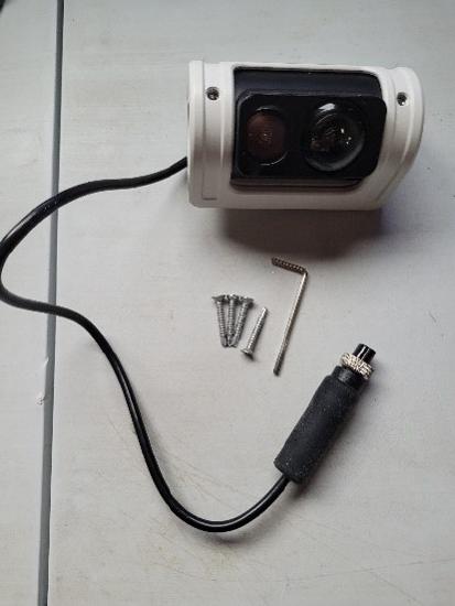
What comes in the box?
|
 |
|
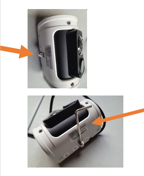
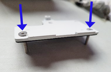
On the side of the camera, at the bottom (see orange arrows), is a mounting plate hex screw.
Using the hex wrench that came in the box, loosen this screw until the bottom plate comes off the bottom of the camera.
|
 |
|
Bottom of the side camera. Note: the black metal plate is only held on with one screw—the screw you just loosened. |
 |
|
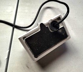
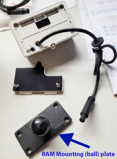
Remove the bottom plate. You will also see the RAM Mounting plate (called a ball plate). Note: the bottom plate has pre-drilled holes with tight rubber. |
 |
|
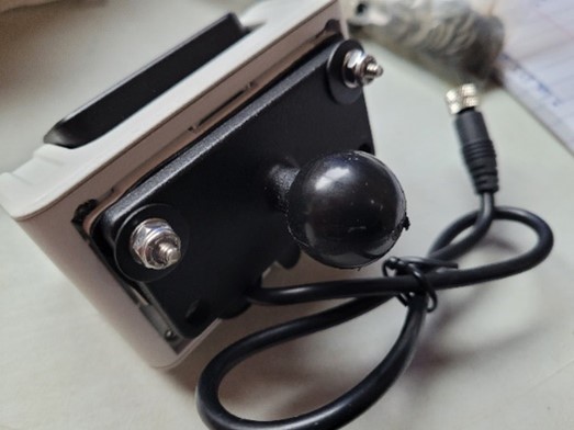
Insert two stainless steel hex bolts in the underside of the bottom camera plate (the white side). |
 |
|
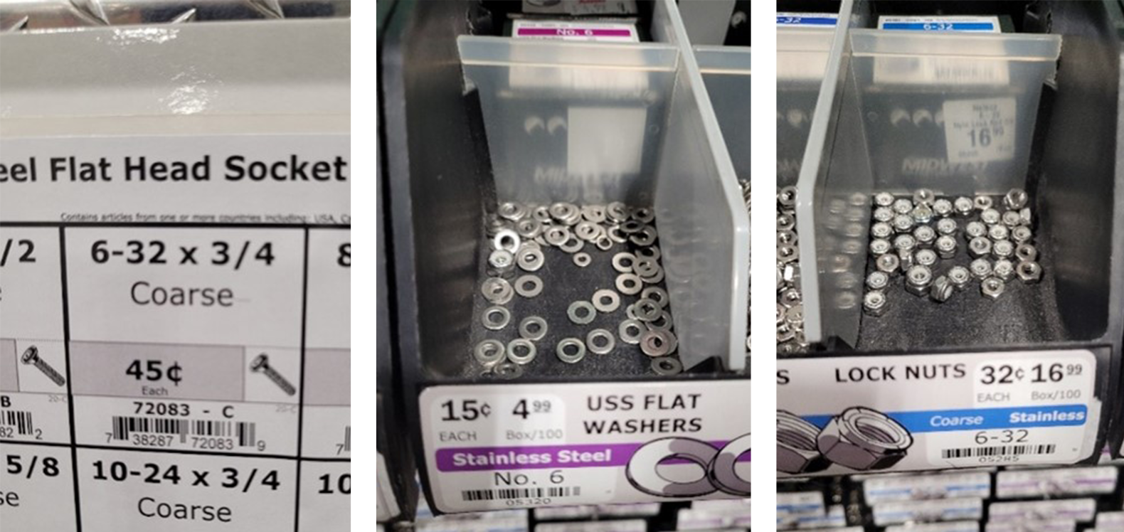
Drop on the RAM ball mounting plate, and then the stainless steel washers. Tighten each bolt down with stainless steel lock nuts. (Note: Need to use lock nuts due to vibration from the road, and stainless steel to avoid rust).
Note: The trio of images to the right indicate the specific stainless-steel hardware used to fasten the RAM ball plate to the camera. If available, one might try a 6-32 x 5/8” bolt (to provide more clearance for the ball mount), but it is not essential. |
|
MOUNTING METHODS/SCENARIOS:
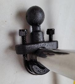
Vehicle Ball Mount Plate - Angled (Best for square or flat stock)
|
Angled Ball Mount Plate: Square Stock Example (ie. some mirrors/rails/sides of trailers and sleeper cab may be square)
|
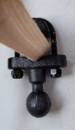
Angled Ball Mount Plate: Round Stock Example (Most mirror frames on sides of vehicle may be round. See next section for round stock mount.)
|
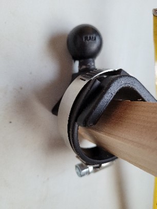
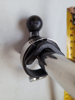
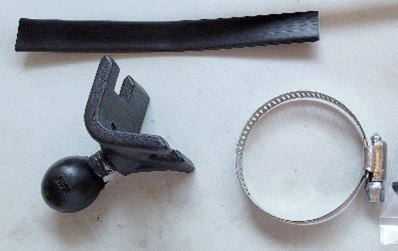
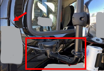
Vehicle Ball Mount Plate - Round (Best for round stock)
|
Round Ball Mount Plate: Round Stock Example
|
Round Ball Mount Plate: Square Stock Example (ie. some mirrors/rails/sides of trailers and sleeper cab may be square)
|
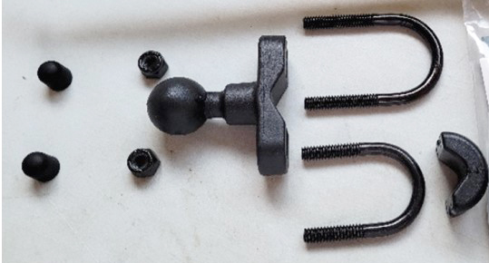
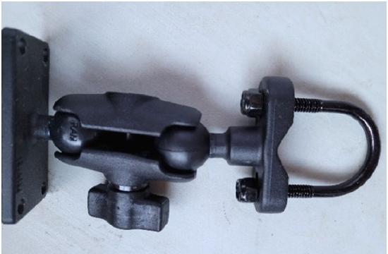
Three Components of the Side Camera Mount
- Adjustment Arm
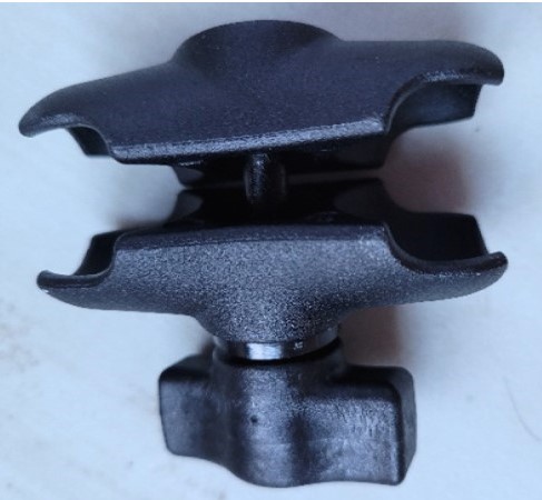
- Vehicle Ball Mount (Pictured on the right, connected to the Adjustment Arm)
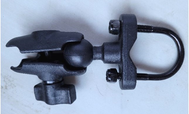
- Camera Ball Mount (Pictured on the left, connected to the adjustment arm + vehicle ball mount)
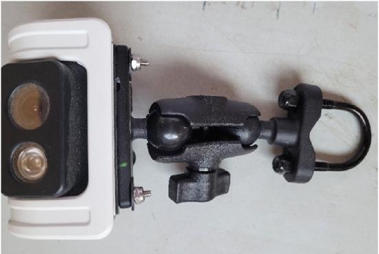
- Entire Mount connected to a side camera.
3) Once the side cameras are mounted, attach the extension cables to their respective side cameras. Be sure to route the cables in such a manner as to avoid excessive wear on the cable where it enters the cab of the vehicle. Additionally, allow enough “play”'slack in the cables to open the doors fully if routing the cable between the door seals. Secure the cables with zip ties or other appropriate mounting material.NOTE: You may want to wrap cable connection points with weatherproof electrical tape to help seal the connections from the elements.
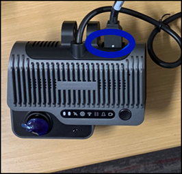
4) Plug the Video Out cable into the main camera. You must remove the rubber port cover at the top of the main camera to expose the Video Out cable port. Align the tab on the cable with the slot on the main camera and push in until secure.
5) Connect the extension cables to the appropriate plug on the Video Out cable, 6 pin to the IPC port and 4 pin to the VIN port
6) Secure all extra cabling with zip ties or other mounting hardware. Tuck it in the headliner, if possible, to keep the extra cabling safely stored and out of the way.
7) Inform your J.J. Keller contact that the Side cameras are installed. The support team can then send the appropriate configuration file to the camera(s) to enable the units. Be prepared to provide the Fleet name, vehicle ID, and Main Camera serial number of each unit that has been installed.
NOTE: The main camera should be “paired” to the vehicle at this point.
Aligning the Side Cameras
To ensure that the side cameras’ fields of view are aligned properly, you will need to login to the local camera with the Veyes app (downloadable from the App store or Google Play) and follow the steps below.
1) Download the Veyes app to your phone or tablet.

2) After ensuring that all camera connection steps above are complete and the main camera is installed in the vehicle, start the vehicle so that the main camera has power. The far-left light should be green and, after about 30 seconds, the Wi-Fi icon will light red. The camera is now in "Wi-Fi Mode".
*Pressing the button 2 times in a row (while vehicle is powered on) will also put the camera in Wi-Fi mode, or "AP Mode". It will only stay in the mode for about 2 minutes.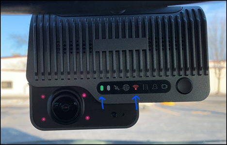
3) Connect your phone or tablet to the camera-hosted Wi-Fi hotspot. Go to the device's Wi-Fi/hotspot connection area (location may vary by device). Look for the hotspot name starting with ST-003Fxxxxxx (the serial number of the main camera).
*Note: If you are not connected to the camera via Wi-Fi, and you try to log in, you will receive a Network Not Available message.
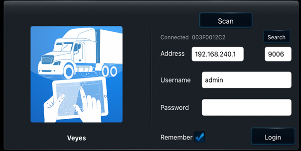
4) Open the Veyes app on your phone or tablet. The default username and password is: admin. Both may already be filled in the Username/Password fields. Click Login.
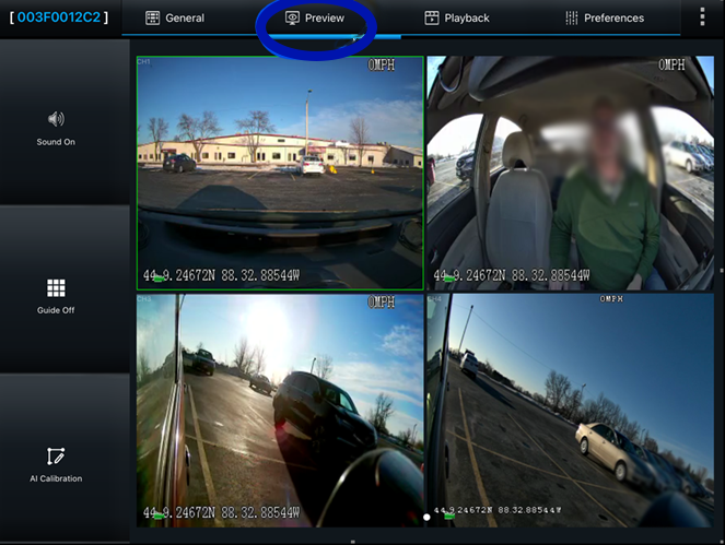
5) Click on the Preview tab at the top of the screen for a live view of the camera images. Use the adjustment screws on the side cameras and the mounting brackets to align the camera’s field of view with the desired area of coverage.
6) Once the cameras are aligned, tighten all adjustment screws and mounting brackets. Secure any wiring that was not secured in the steps above.