Dash Camera 220(S/D) Quick Installation Guide
This article provides step-by-step instructions for installing J. J. Keller® Encompass and VideoProtects™ road- and dual-facing dash cameras. The process includes determining proper windshield positioning, mounting the bracket, installing the camera, connecting it to power via one of 4 methods (9-pin, OBD-II, hardwire, or cigarette adapter), securing cables, and validating operation. It emphasizes correct placement for optimal performance, proper cable routing to ensure safety, and professional installation for hardwiring when needed. The guide also details optional wiring connections for advanced features like Lane Departure alarms and offers contact information for purchasing parts or technical assistance.
These instructions are valid for road- and dual-facing J. J. Keller® Encompass and VideoProtects™ dash camera styles.
Jump to Steps:
Determine Camera Positioning > Install the Bracket > Install the Camera > Connect to Power > Secure the Cables > Validate Operation
Determine Camera Positioning
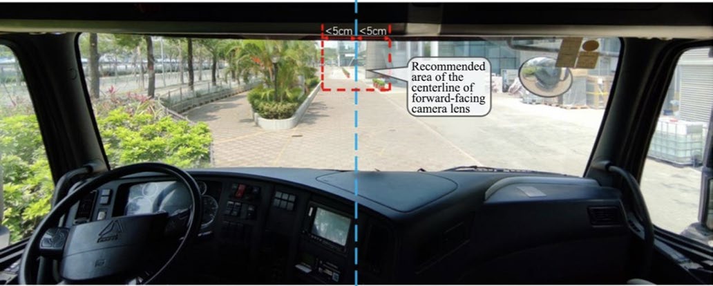
- The camera must be installed on the windshield as high as possible, and as near to the center line as possible. For optimal performance, camera placement should be within 5cm of the center line.
- DO NOT place the camera where it will block the driver's safe view of the roadway.
- The camera lens must be located within the operational area of the windshield wipers.
Note: The camera will not function correctly if mounted upside down; confirm it is placed on the windshield correctly.
Install the Bracket
- Clean the interior glass of the installation area with an alcohol wipe to ensure strong adhesion of the mounting bracket. Before mounting, confirm the glass is dry.
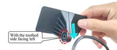
- Align the mounting bracket with the connection of the bracket facing down (grooved/”toothed” side facing the driver)
- Remove the 3M adhesive on the bracket and position it on the front windshield. Apply pressure on the bracket for 10 seconds to remove air bubbles between the bracket and the glass.
Install the Camera
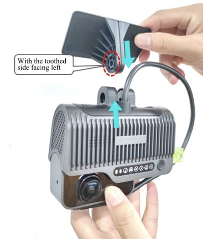
- Connect the camera to the bracket with the front side facing inward—with the grooves/teeth on the left side of the bracket engaged with those on the left inner side of the camera.
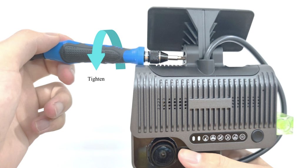
- Tighten the bracket bolt clockwise. Before tightening completely, adjust the camera on the dash to be as close to vertical as possible.
Connect to Power Supply
Power can be supplied to the Dash Cam one of four ways:
- 9-pin (Wiring Kit & Y-Splitter sold separately)
- OBD-II (Wiring Kit & Y-Splitter sold separately)
- Cigarette Adapter (Sold separately)
- Hardwire connection (Included in Dash Camera box)
Contact your J. J. Keller representative to order separate parts or call 855.693.5338.
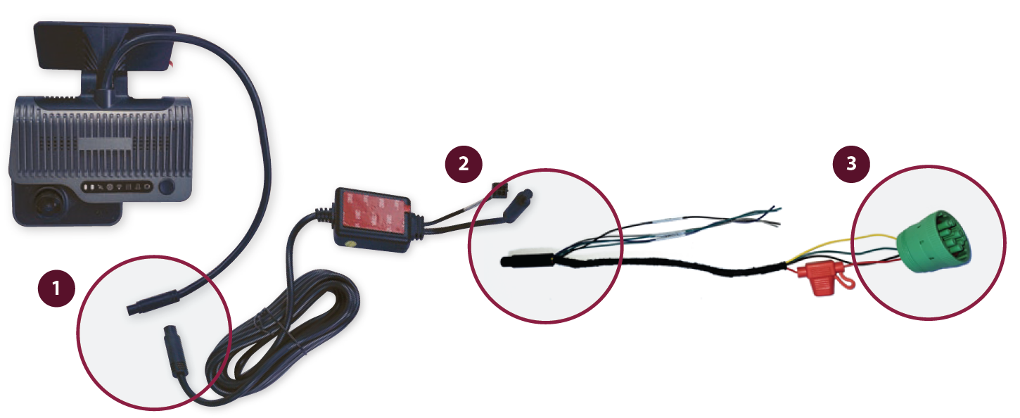
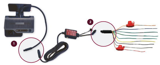
9-Pin Installation
|
Without Y-Splitter
Route cables and secure with zip ties.
|
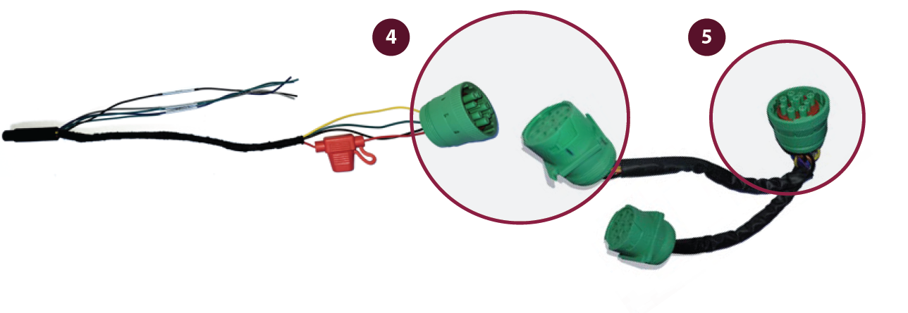
With Y-Splitter Follow steps 1-2. 4. Plug male end of the 9-pin connector into one of the female Y-splitters. 5. Plug the male end of the Y-splitter into the vehicle’s diagnostic port. Route cables and secure with zip ties.
|
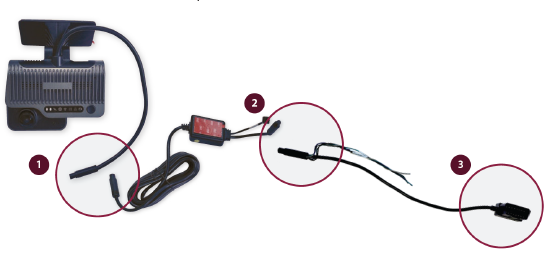
OBD-II Installation
|
Without Y-Splitter 1. Plug the female connector from the camera into the male end of the 2. Connect the female end of the power box harness to the male end of the OBD-II connector. 3. Plug the OBD-II harness directly into the vehicle’s diagnostic port. Route and secure the cables with zip ties.
|
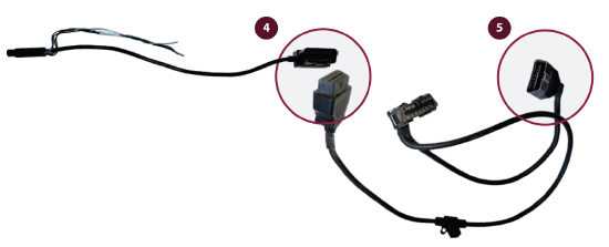
With Y-Splitter Follow steps 1-2. 4. Plug the male end of the OBD-II connector into one of the female Y-splitters. 5. Plug the male end of the Y-splitter into the vehicle’s diagnostic port. Route and secure cables with zip ties.
|
Dash Camera Part Update - RP1226 Power Adapter
Recent OEM guidance indicates that the RP1226 port is the preferred connection point for fleet management devices such as ELD, Asset Trackers and Dash Cams in vehicles that are equipped with RP1226 ports.
Furthermore, the guidance states that these ports should be used in a one-to-one configuration, meaning 1 device per port due to the possibility of signal interference and/or excess voltage usage if a Y harness or splitter is used to connect multiple devices to the same port. Many newer vehicles come with multiple RP1226 ports pre-installed to support this new guidance.
Here is further information on the part numbers:
- When using the vehicle's RP1226 port to power the dash cam, the correct Part Number will be: 75029 - DASH CAM RP-1226 POWER ADAPTER
- This adapter works with both the VP220 and VP240 series main line dash cameras.

*Note: We are working with our vendor to have the portion circled above, removed, as this would further align with OEM guidance.
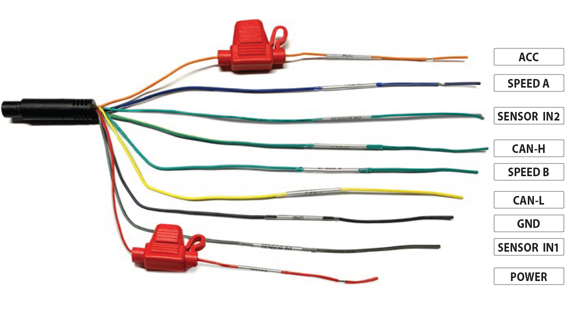
Hardwire Connection Installation
Professional installation is recommended. Contact your J. J. Keller sales representative for a quote on installation or use a skilled technician.
|
1. Plug the female harness from the camera into the male end of the power box harness. |
 |
|
3. Connect ACC to the ignition signal cable of vehicle 12. Route and secure cables with zip ties |
 |
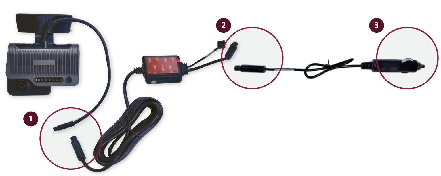
Cigarette Adapter
This method is not recommended for non-trial cameras.
- Plug the female harness from the camera into the male end of the power box harness.
- Connect the female end of the power box harness to the male end of the cigarette adapter.
- Plug the cigarette adapter into the vehicle’s auxiliary power port.
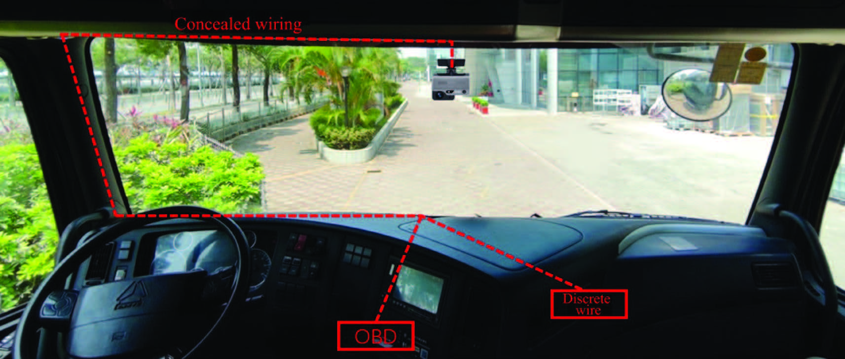
Secure Cables
- Secure all cables by routing them under the headliner and behind the trim panels, or with zip ties and mounting blocks.
- Securely fasten any cables under the dash, up and out of the way of the operator.
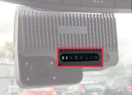
Validate Power
- Verify all power cables are connected.
- Turn on the vehicle’s engine and wait two minutes.
- The dash cam power light in the status bar should be green.
- Remove the blue protective film from the lens.
NOTE: The four infrared lights surrounding the driver-facing camera may be visible depending on the ambient light conditions inside the vehicle.
Disclaimer: Many states have laws that either restrict or prohibit mounting objects on windshields. Specific laws vary from state to state. Before mounting the Dash Cam Pro, check the state and local laws and ordinances where you drive. It is the user’s responsibility to mount the Dash Cam Pro in compliance with all applicable laws and ordinances. J. J. Keller does not accept responsibility for any fines, penalties, or damages that may be incurred as a result of any state or local law or ordinance relating to your use of the Dash Cam Pro.