Dash Camera 240(S/D) Quick Installation Guide
This article provides step-by-step instructions for installing J. J. Keller® Encompass and VideoProtects™ road- and dual-facing dash cameras. The process includes determining proper windshield positioning, mounting the bracket, installing the camera, connecting it to power via one of 5 methods (12V Auxiliary, 9-pin, OBD-II, RP-1226 or Hardwire), securing cables, and validating operation. It emphasizes correct placement for optimal performance, proper cable routing to ensure safety, and professional installation for hardwiring when needed. The guide also details optional wiring connections for advanced features like Lane Departure alarms and offers contact information for purchasing parts or technical assistance.
These instructions are valid for road- and dual-facing J. J. Keller® Encompass and VideoProtects™ dash camera styles.
Jump to Steps:
Install Mounting Bracket > Determine Position of Camera > Install the Camera > Connect to Power Supply > Validate Power > Secure Cables
Install the Mounting Bracket
- Align the bracket hole with the 2 mounts on the top of the dash cam. The grooved hole must face right away from the driver's window, indicated by the arrow.

- Insert the bolt and adjust the camera to the vertical position relative to the bracket. Tighten clockwise with #2 Phillips head screwdriver until snug.
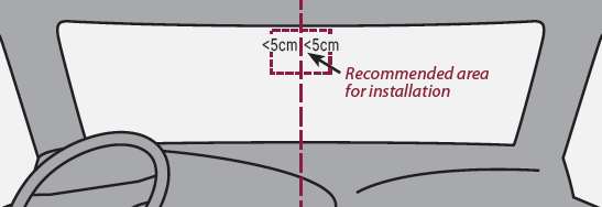
Determine Position of Camera
Determine the ideal position of the camera.
- The camera should be installed as close as possible above the horizontal middle of the windshield and within 2 inches (5 cm) of vertical center.
- Position camera within the working range of the windshield wipers.
- Ensure camera does not block driver's vision.
Install the Camera
- Clean the interior glass around the installation area with the alcohol wipe included in the box to promote strong adhesion of the mounting bracket. Ensure the glass is dry before application.
- Remove the protective film from the mounting bracket and position the bracket in the area identified in the image from the previous section.
- Apply pressure on the bracket for 10 seconds to remove air bubbles between the bracket and the glass.
- Adjust camera tilt as shown in the image below.

- Tighten the bracket screw to secure in position.
Connect to Power Supply
Power can be supplied to the main camera in 1 of 5 ways:
- 12V Auxiliary Power Adapter (Included with Trial Kits)
- 9-pin (Harness Kit* sold separately)
- OBD-II (Harness Kit* sold separately)
- RP-1226 (Power Adapter sold separately)
- Hardwire Connection (Included in Dash Camera box)
*Harness Kits allow additional telematic device connections to the diagnostic port.
Before plugging the power cable into the main camera, plan the route of the cable, which may include routing through the A- or B-pillar or headliner based on your preference.

See below for specific instructions for your chosen power supply option.
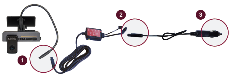
12V Auxiliary Power Adapter
- Plug female harness from the camera into male end of the power box harness.
- Connect female end of the power box harness to male end of 12V auxiliary power adapter.
- Plug 12V auxiliary power adapter into vehicle's 12V auxiliary power outlet.
Proceed to the next step, Validate Power.
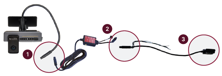
9-pin
|
Without Y-Splitter
Proceed to #4 With Y-Splitter or Validate Power.
|
With Y-Splitter Follow steps 1 and 2.
Proceed to Validate Power.
|


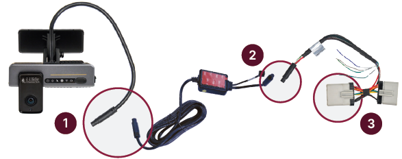
OBD-II
|
Without Y-Splitter
Proceed to #4 With Y-Splitter or Validate Power.
|
With Y-Splitter Follow steps 1 and 2.
Proceed to Validate Power.
|

RP-1226
- Plug female connector from camera into male end of the power box harness.
- Connect female end of power box harness to male end of 10 pin cable on the RP-1226 power adapter connector.
- Plug male end of RP-1226 power adapter into vehicle’s RP-1226 female port.
Proceed to Validate Power.
Hardwire Connection
*Professional installation is recommended. Contact your J. J. Keller Sales Representative for a quote on installation or use a skilled technician.
|
 |
|
The first 3 wires must be connected for the camera to operate properly.
The remaining wires are not required, except for those that become optional when the Lane Departure Warning (LDW) alarm is enabled.
Proceed to Validate Power. |
 |
Validate Power
- Verify all power cables are connected.
- Turn on the vehicle's engine and wait 2 minutes.
- The dash cam power light icon (far left) in the status bar should be solid green.
- Remove the blue protective film from the lens.

Note: The 4 infrared lights surrounding the driver-facing camera may be visibile depending on the ambient light conditions inside the vehicle.
Secure All Cables
- Secure all cables by routing them under the headliner and behind the trim panels, or secure with zip ties and mounting blocks.
- Securely fasten any cables located under the dash so they are out of the way of the operator.
Disclaimer: Many states have laws that either restrict or prohibit mounting objects on windshields. Specific laws vary from state to state. Before mounting the dash camera, check the state and local laws and ordinances where you drive. It is the user’s responsibility to mount the dash camera in compliance with all applicable laws and ordinances.J. J. Keller & Associates, Inc. does not accept responsibility for any fines, penalties, or damages that may be incurred as a result of any state or local law or ordinance relating to your use of the dash cam.